
For drilling projects, operational success and safety rely on the seamless integration of your blowout preventer (BOP) stack, high pressure test unit, and control panel. A complete well control solution is more than just a collection of hardware; it is an engineered ecosystem where every component must be perfectly calibrated to ensure pressure integrity.
This guide outlines the standard configuration rules to help you design an integrated well control equipment package that meets rigorous field demands.
A robust system requires clear functional alignment among its three pillars to ensure operational safety and pressure integrity. Each component serves a distinct yet interdependent role:
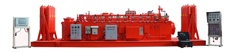
This assembly serves as the primary physical barrier. It provides the mechanical force necessary to seal the wellbore instantly during kick hazards or emergency situations, effectively preventing uncontrolled fluid flow to the surface.
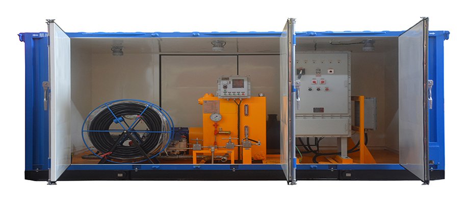
This unit acts as the reliability gatekeeper. It undertakes regular hydraulic testing to verify that the BOP stack, valves, and piping can withstand their rated operational pressures, ensuring that every pressure-containing component remains fit for service before drilling commences.
This device functions as the command center for the entire well control ecosystem. It realizes precise backpressure regulation by managing the choke valves and enables unified, remote operation for the assembly, allowing drillers to respond to wellbore pressure fluctuations with controlled precision.
All devices must strictly follow API 16D and API 16C standards to ensure technical compatibility. When designing your well control system configuration, engineers must ensure that pressure ratings, hydraulic interface specifications, and electronic signal protocols are fully unified. Proper pressure matching across these components prevents performance bottlenecks, ensuring stable linkage and high-precision testing accuracy during critical well control operations.
To ensure the rig's pressure containment remains robust under varying geological demands, the hardware package must be scaled specifically to the wellbore profile:
Configures a basic BOP stack with a general-purpose, skid-mounted test unit. This primary setup prioritizes simplicity and field-replaceability, ideal for standard vertical drilling where rapid rig-up/rig-down is the operational focus.
Integrates 35MPa+ rated BOP assemblies with high-flow hydraulic test units. This configuration requires redundant accumulators and heavy-duty seals to mitigate the fatigue associated with high-pressure gas zones or extended reach drilling.
Utilizes high-grade, corrosion-resistant alloy components and explosion-proof remote control interfaces. The setup must include failsafe hydraulic circuits that maintain barrier integrity even if the primary power source is interrupted.
Before the equipment goes live, the assembly must pass an integrated validation protocol rather than just component-level testing. The commissioning team should execute the following sequence:
Cycle all actuators from the remote control panel and the BOP stack simultaneously to identify pressure drops or internal leakage in the manifold.
Measure the response time from the console command to the valve actuation. Any lag exceeding manufacturer specifications must be corrected to ensure the system meets rapid-response requirements for well control.
Perform a full-rated pressure test on the entire integrated loop for at least 15 minutes to confirm that every connection—from the test unit to the BOP seals—maintains zero pressure loss.
Intentionally trigger an emergency shutdown (ESD) to ensure the BOP enters the default "safe" position without operator intervention.
Different site environments necessitate specific design approaches to maintain operational efficiency and safety:
Favor portable test units and compact combined systems to allow for flexible deployment and rapid relocation between sites.
Utilize fixed test units and integrated master consoles to facilitate high-volume, batch testing tasks with maximum precision.
Select specialized materials with extreme temperature tolerance and enhanced sealing structures to prevent mechanical failure due to thermal expansion or contraction.
These targeted strategies for onshore well control, offshore well control, and high pressure well control are critical to minimizing downtime and maximizing the return on your equipment investment.
Operational downtime and safety risks often stem from subtle configuration oversights that occur during the initial design phase:
Installing a 21MPa test unit on a 35MPa BOP stack is a frequent, critical error. Always verify the maximum allowable working pressure (MAWP) of the weakest link in the chain; the entire system's rating is capped by that component.
Using mineral-based fluid in systems sealed for fire-resistant synthetic fluids can cause rapid seal degradation. Ensure all hydraulic connectors are standardized across the test unit and BOP actuators to prevent fluid cross-contamination and connection leaks.
Often, teams overlook the integration of the control panel with the BOP's position sensors. Without this linkage, the operator loses critical "state awareness," leading to potential misfires during well-kill operations. The solution is to conduct a pre-installation protocol review to match interface specifications before hardware reaches the rig floor.
Beyond the three core devices, a full set well control equipment package can be further enhanced with 35MPa pump valves and dedicated hydraulic fluids. Integrating these high-quality accessories ensures that the entire pressure loop operates at peak efficiency, preventing premature wear on valve seats and actuator seals.
Reasonable configuration and precise matching of the BOP, test unit, and control panel are the foundations of safe and efficient drilling. By following these well control system configuration guidelines, engineering teams can successfully deploy a robust, compliant, and reliable solution.
For technical support in designing a well control turnkey solution tailored to your specific drilling program, feel free to consult with our engineering team for expert guidance.
By continuing to use the site you agree to our privacy policy Terms and Conditions.

