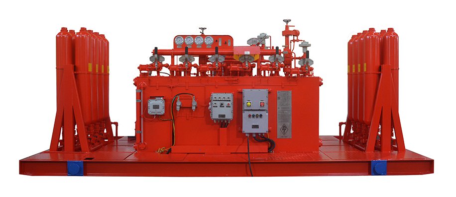
An accumulator unit stores hydraulic energy for BOP emergency operations. It supplies pressurized fluid when preventers need to close, helping maintain well control when rapid hydraulic response is required. Its capacity, pressure, and condition all affect emergency readiness.
An accumulator vessel uses compressed nitrogen to store energy. When hydraulic fluid enters the vessel, the gas compresses. When the control system requires fluid, the expanding nitrogen pushes the stored fluid back into the hydraulic circuit.
A bladder or piston separates the gas from the hydraulic fluid, depending on the accumulator design. The nitrogen precharge must remain within the manufacturer's specified range to maintain proper operation.
During BOP operations, the accumulator bank works with hydraulic pumps, control valves, and the control manifold to make stored energy available.
Hydraulic pumps: Charge the accumulator bank before operation.
Control valves: Direct stored fluid to the required BOP functions.
Control manifold: Distributes hydraulic fluid to selected actuators.
Pressure gauges: Help operators monitor system pressure.
The accumulator bank provides the stored energy, while these components manage its delivery. This coordination allows the BOP control system to operate the required preventer functions.
When an abnormal well condition requires preventer closure, the control system directs pressurized fluid to the selected actuator. The accumulator bank supplies the hydraulic energy needed to operate the closing mechanism.
Depending on the installed configuration, this supports ram and annular preventer functions. The available fluid must meet the hydraulic demand of the required operations, including functions performed in sequence.
If a hydraulic pump stops because of an electrical interruption or mechanical fault, the accumulator bank can supply stored fluid for required operations.
The available reserve depends on the remaining usable fluid volume and pressure. Operators must confirm that the stored energy can support the required BOP functions.
Some configurations also include a separate nitrogen backup system. This provides an additional pressure source and is different from the nitrogen precharge inside an accumulator vessel.

The nominal volume of an accumulator vessel is not the same as the usable hydraulic fluid volume. The amount of fluid available for operation depends on factors such as nitrogen precharge, working pressure, and the system's operating range.
Capacity selection must account for the hydraulic demand of the connected BOP equipment and the sequence of required functions. Simply adding the nominal volumes of all vessels does not establish the usable reserve.
The accumulator bank's working pressure must be compatible with the BOP control system and its connected equipment. Buyers should evaluate pressure ratings together with accumulator quantity and usable fluid volume.
The following specifications compare two BOP control system models:
| Specification | FKQ640-6 | FKDQ1280-8 |
| Accumulator Quantity | 16 | 32 |
| Volume per Accumulator | 11 gallons | 11 gallons |
| Listed Working Pressure | 21 MPa | 21 MPa |
These figures are specific to the listed models. The 11 gallon value refers to the nominal capacity of each vessel, not the usable hydraulic fluid volume. For example, the FKQ640-6 control system is listed with 16 accumulators, each with an 11 gallon capacity.
A BOP control system may connect several accumulator vessels in one bank. This arrangement provides hydraulic storage and can help maintain system availability if an individual vessel becomes unavailable.
The actual reserve depends on the number of vessels, their capacity, system layout, and hydraulic demand. Redundancy should therefore be assessed against the specific equipment configuration.
The BOP control system information published for a specific design states that total capacity loss does not exceed 25% when one or more accumulators fail.
This figure applies only to that design and should not be treated as a universal industry requirement. Buyers should review the accumulator arrangement and remaining capacity under the stated failure conditions.
Pressure readings help operators identify changes that may affect accumulator performance. Checks should follow the equipment manual and site maintenance plan. They may include:
Accumulator and nitrogen precharge pressure.
Hydraulic pressure at the control manifold.
Annular pressure and relevant circuit readings.
Air supply pressure, where applicable.
Hydraulic fluid level, connections, and visible leakage.
Abnormal readings should be investigated before the system is relied on for emergency operations.
Maintenance may include checking vessel wall thickness, measuring nitrogen pressure, and inspecting the bladder where applicable. A damaged bladder can affect gas and fluid separation, reducing accumulator performance.
An offshore BOP control system maintenance project included wall thickness inspection, nitrogen pressure detection, and bladder replacement. The offshore accumulator maintenance case provides an example of these inspection activities.

Cost factors include accumulator quantity, vessel capacity, working pressure, system configuration, testing, and service requirements.
An existing accumulator bank may be upgraded if its pressure ratings, hydraulic connections, control design, and installation space allow it. Usable fluid capacity must also meet the required BOP functions.
Operating pressure, usage, maintenance, and component condition all affect service life. Follow the manufacturer's inspection and replacement recommendations.
Suitable capacity, compatible pressure, and regular maintenance help keep BOP accumulator units ready for emergency operations. For configuration or service support, contact the Dongsu engineering team.
By continuing to use the site you agree to our privacy policy Terms and Conditions.