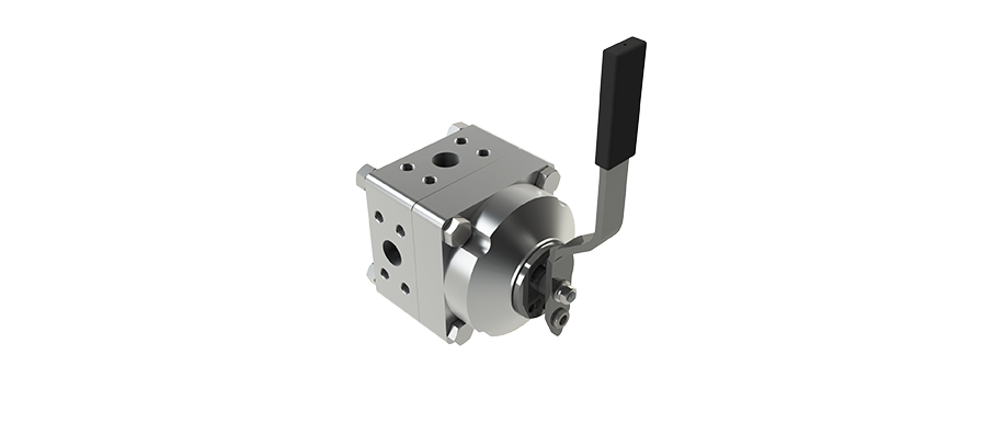
Rotary valves control fluid direction by turning an internal valve element to connect or block specific flow passages. In industrial hydraulic systems, this mechanism helps operators manage fluid distribution, switch operating states, and control hydraulic actuators. Understanding their structure and working principle is important when selecting valves for high pressure applications.
A rotary valve uses a rotating core, spool, or internal passage to change the connection between hydraulic ports. Unlike a linear valve that moves along an axis, a rotary valve changes the flow path through angular movement.
Depending on its design, the valve can direct pressurized oil to different outlets, block a passage, or connect a working line to the return circuit. This makes it suitable for directional control in hydraulic equipment.
A typical hydraulic rotary valve consists of several functional parts:
Valve body: Contains the internal passages and external ports.
Rotary core or spool: Changes the connections between ports when turned.
Sealing components: Limit internal and external leakage.
Operating handle or actuator: Provides the force needed to change valve position.
The design of the sealing interface is particularly important in high pressure systems, where leakage can affect control accuracy and operating reliability.

A 3 position 4 way rotary valve has three selectable positions: left, center, and right. Each position establishes a specific internal flow arrangement.
When the operator turns the handle, the valve core rotates and changes which passages are connected. The selected position determines how hydraulic oil moves through the circuit.
The four ports typically include:
P: Pressure oil inlet.
T: Return oil outlet.
A: First working port.
B: Second working port.
The valve directs pressure oil from P toward A or B according to its internal configuration. The other working port may connect to T, allowing the actuator to move in the opposite direction. The exact connections in the center position depend on the valve design.
| Valve Element | Function | Control Effect |
| Three operating positions | Selects left, center, or right state | Changes the flow arrangement |
| P and T ports | Connect pressure supply and return lines | Establishes the hydraulic supply path |
| A and B ports | Connect to working circuits | Directs oil to actuators |
| Rotary core and seals | Switch and seal internal passages | Supports controlled flow switching |
In surface BOP control systems, rotary valves help direct hydraulic oil to selected control circuits. Operators use the valve position to manage hydraulic flow for the operation of actuators and other control components.
DONGSU's BOP hydraulic control system uses hydraulic control components to operate blowout preventer functions. Within this type of system, directional valves help connect the pressure supply to the required operating circuit.

Oilfield hydraulic equipment operates under demanding pressure conditions. Valve sealing, material suitability, and connection design therefore affect system reliability.
DONGSU's 3-Pos.4-Way Rotary Valve is designed for oilfield control systems, particularly surface BOP control units. Its shear type structure uses a wave spring to provide initial sealing pressure, while hydraulic pressure helps strengthen the sealing effect under higher pressure conditions.
Check the number of positions, port arrangement, connection size, and required flow paths. A three position four way valve should match the circuit diagram and the operating sequence of the connected equipment.
The rated working pressure must meet the system requirements. Also consider hydraulic fluid compatibility, sealing materials, operating temperature, and the risk of contamination.
For oilfield applications, connection standards and installation conditions should be confirmed before ordering. A valve that fits the pressure rating but does not match the circuit configuration may still cause operating problems.

Regular inspection helps identify leakage, difficult handle movement, abnormal resistance, and damage to sealing surfaces. Contamination in hydraulic oil should also be controlled because particles can affect valve movement and sealing performance.
During maintenance, check whether each operating position produces the expected flow path. Confirm that the connected actuators respond correctly and that the valve returns to the required state without abnormal leakage.
A rotary valve changes flow paths through rotational movement, while a linear valve uses axial movement to open, close, or regulate passages.
Yes. A directional rotary valve can route pressurized oil to different actuator ports, allowing hydraulic cylinders or other components to move according to the selected flow path.
Possible causes include worn seals, damaged sealing surfaces, contamination, incorrect installation, or operating conditions beyond the valve's rated limits.
Rotary valves provide a practical way to switch hydraulic flow paths in industrial control systems. Correct port configuration, pressure rating, and sealing design are essential for reliable operation. For rotary valve solutions used in oilfield hydraulic systems, contact the DONGSU team to discuss your application requirements.
By continuing to use the site you agree to our privacy policy Terms and Conditions.