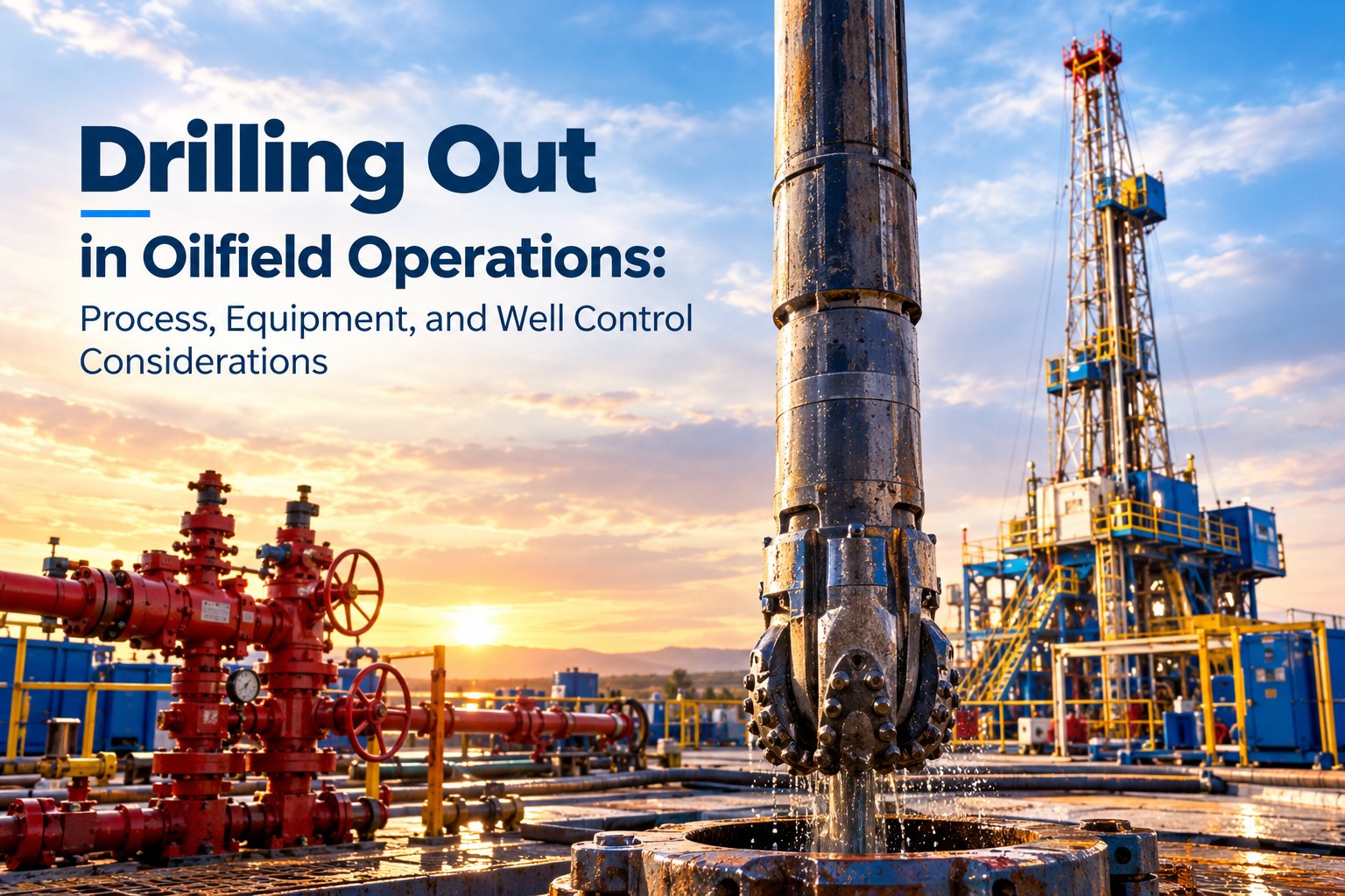
Drill out operations require careful planning because plug removal can affect circulation, pressure conditions, and wellbore access. Selecting the appropriate intervention method and verifying surface equipment readiness are essential to maintaining operational control.
This article examines the drill out workflow, key equipment requirements, and practical measures for managing well control risks and reducing non productive time.
Drill out operations commonly involve milling composite frac plugs, drillable isolation plugs, or residual cement after hydraulic fracturing. These barriers isolate sections of a well during stimulation. Once the required stages are complete, crews remove them to restore wellbore access.
The milling method depends on plug material, well geometry, and intervention equipment. Operators must confirm the completion design before selecting suitable tools and operating parameters.
A typical campaign includes five stages:
Rig up: Install intervention and pressure control equipment.
Verify barriers: Inspect relevant components and complete required pressure tests.
Mill plugs: Deploy the milling assembly using coiled tubing or jointed pipe, as appropriate.
Remove debris: Circulate milled material toward the surface while monitoring returns.
Confirm access: Verify the required depth and wellbore condition before proceeding.
The sequence varies by well and intervention method. Circulation, milling performance, and returns must be monitored throughout the operation.
The downhole assembly performs the actual plug removal. Depending on the application, it may include a milling bit, downhole motor, coiled tubing or jointed pipe, and supporting measurement equipment.
Selection depends on plug construction, lateral length, expected debris volume, and the required reach. Appropriate circulation practices are also necessary to transport cuttings and reduce the risk of debris accumulation.

Surface equipment provides pressure containment and supports well control during intervention. Depending on the well conditions and operating method, the configuration may include a blowout preventer (BOP), valves, pressure rated connections, and other intervention pressure control components.
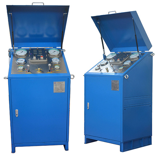
A suitable BOP control system operates surface mounted BOPs and may also control associated hydraulic choke, kill, and diverter equipment, depending on its configuration. The system must match the installed equipment and the approved well control requirements.
The BOP control unit operates the preventer system; it does not perform downhole milling. This distinction helps operators select equipment according to its intended function.
Before intervention begins, crews should inspect pressure retaining components, seals, valves, connections, and control lines. Equipment ratings and compatibility must be suitable for the planned operation.
Hydraulic pressure testing helps verify the integrity of applicable pressure containing equipment. Test pressures, hold periods, and acceptance criteria must follow the approved procedure and relevant standards.
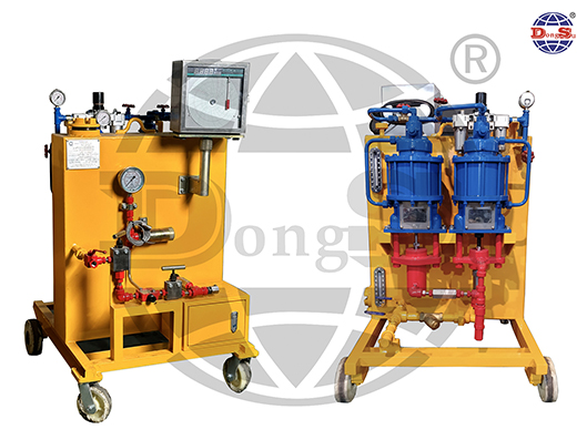
A high pressure test unit can support hydraulic testing of BOP stacks, choke manifolds, casing heads, valves, and other pressure bearing components. The unit must be suitable for the component and required test conditions.
Test results should be recorded and reviewed before work proceeds. Leakage or unexplained pressure loss requires investigation and resolution.
Pressure testing should be accompanied by functional checks and verification of the planned barrier arrangement. Depending on the system, checks may include control power, accumulator condition, emergency shutdown functions, and communication procedures.
The pre job review should establish responsibilities, monitoring requirements, and stop work criteria so personnel understand how to respond to abnormal conditions.
Milling through a plug can change flow conditions and expose the wellbore to previously isolated sections. Depending on reservoir pressure and barrier conditions, pressure fluctuations or unexpected fluid influxes may occur.
Operators should monitor pressure readings, circulation rates, and return volumes. Unexpected changes may indicate altered downhole conditions, restricted circulation, or a developing well control issue.
Maintaining the required relationship between wellbore pressure and formation pressure is essential to preventing unwanted influxes. Responses to abnormal conditions must follow the approved well control program.
Where active surface pressure regulation is required, a choke manifold helps control returning fluids and maintain the specified pressure conditions. Choke settings must reflect actual well behavior and remain within approved operating limits.
A choke manifold control panel operates the hydraulic choke manifold and, depending on the model, supports remote valve control and monitoring of operating parameters.
Choke adjustments must follow the designated procedure. They should not replace proper pressure monitoring or the established response to a suspected influx.
Excessive milling loads, unsuitable operating parameters, and inadequate debris transport can contribute to motor stalls, restricted circulation, and stuck intervention equipment.
Operators should follow the milling program, monitor torque and differential pressure where available, and maintain circulation suitable for the well geometry. Observing returns can help identify poor hole cleaning before debris accumulation causes more serious disruption.
Leaking connections, damaged seals, and equipment failures can interrupt operations. Inspection and maintenance should reflect equipment specifications, operating conditions, and service history.
Confirming equipment readiness before mobilization and addressing identified defects can reduce avoidable downtime. Emergency shutdown capabilities and backup arrangements should also be verified as part of the well control plan.
Selection depends on plug material, well geometry, intervention method, debris volume, circulation requirements, and well pressure. Surface pressure control equipment must also meet the planned operating requirements.
Pressure testing helps verify the integrity of applicable pressure retaining components. It should be combined with inspections, functional checks, and documented acceptance criteria.
Common causes include milling difficulties, inadequate debris removal, circulation restrictions, equipment failures, and unexpected well conditions. Proper planning and timely responses to abnormal indicators help reduce interruptions.
Reliable drill out operations depend on suitable equipment and effective well control planning. If you are evaluating BOP control systems, pressure testing equipment, or choke manifold control solutions for your drilling project, contact DONGSU to discuss your operational requirements and identify suitable equipment options.
By continuing to use the site you agree to our privacy policy Terms and Conditions.